
1. Functional Description
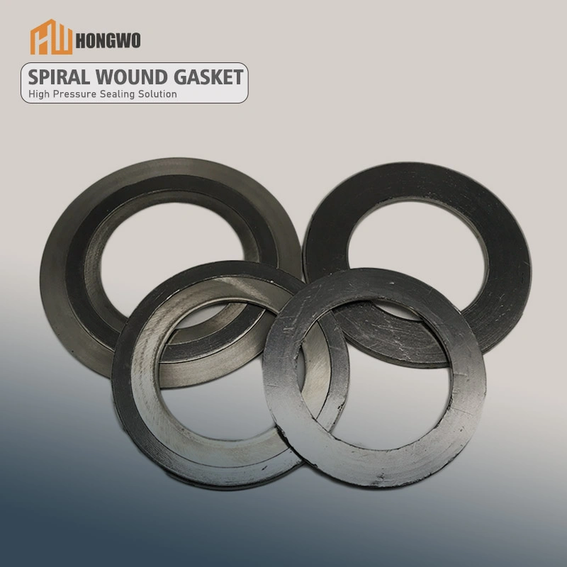
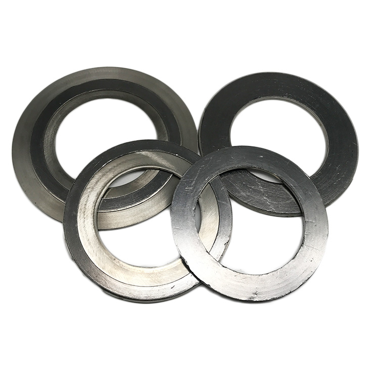
Spiral wound metal gaskets are precision-engineered sealing components designed for extreme industrial environments. They consist of alternating layers of V-shaped metal winding strips (commonly stainless steel 304/316, titanium, or Inconel) and non-metallic filler materials (e.g., flexible graphite, PTFE, or mica) spirally wound under controlled tension. This hybrid structure provides dual sealing mechanisms:
- Metal strips ensure mechanical strength and resilience under thermal cycling.
- Filler materials achieve leak-tight sealing by conforming to flange surface imperfections.
Key performance advantages include:
- Wide temperature range: -200°C to +800°C continuous operation.
- Pressure resistance: Up to 3,000 psi (206 bar) static and dynamic loads.
- Chemical compatibility: Resistant to acids, alkalis, hydrocarbons, and steam.
2. Engineering Data Validation
2.1 Compression-Recovery Testing
Independent lab tests validate a minimum 15% recovery rate after 50% compression (ASTM F586 standards), ensuring long-term sealing integrity under cyclic loads.
2.2 Leakage Rate Certification
- Helium leak rate: ≤1×10⁻⁹ mbar·L/s (EN 13555 Class L0.1).
- Hot tightness: Maintains sealing at 600°C for 500 hours (API 601/6G specifications).
3. Scenario-Based Applications
3.1 Oil & Gas Pipeline Flanges
- Case: Offshore platform gas compression systems (API 6A/6BX flanges).
- Solution: SS316L + PTFE gaskets prevent sour gas (H₂S) corrosion and thermal creep at 450°C/2,200 psi.
3.2 Chemical Reactor Manways
- Case: Polyethylene reactor manway sealing (ASME B16.20 flanges).
- Solution: Inconel 625 + expanded graphite gaskets withstand 98% sulfuric acid exposure at 300°C.
4. Compatibility & Selection Guide
4.1 Material Pairing Matrix
| Metal Strip | Filler | Compatible Media |
|---|---|---|
| SS304 | Flexible Graphite | Steam, hydrocarbons, mild acids |
| Titanium | PTFE | Chlorides, nitric acid, solvents |
| Inconel 625 | Mica | Molten salts, superheated steam |
4.2 Flange Surface Requirements
- Ra ≤ 3.2 μm (ASME B16.5).
- Avoid serrated flanges with spiral wound gaskets; use flat-face or raised-face designs.
5. Installation Protocol
5.1 Pre-Installation Checks
- Inspect flange surfaces for scratches or pitting (reject if defects exceed 0.05mm depth).
- Clean residual sealant from flange grooves with non-abrasive tools.
5.2 Torque Sequence
- Step 1: Hand-tighten bolts in a star pattern.
- Step 2: Apply 30% final torque, then 60%, and finally 100% in three passes.
- Torque values: Refer to ASME PCC-1 guidelines (e.g., 120 N·m for M24 bolts).
6. Safety Warnings
- DO NOT reuse gaskets after disassembly; plastic deformation compromises sealing.
- Avoid over-compression: Exceeding 50% strain causes filler extrusion and metal strip buckling.
7. Common Installation Errors
7.1 Misalignment
- Error: Installing gaskets with misaligned inner/outer rings.
- Consequence: Uneven stress distribution → flange warpage.
7.2 Incorrect Filler Selection
- Error: Using PTFE filler in >260°C oxygen-rich environments.
- Risk: PTFE decomposition → toxic gas release.
8. Maintenance & Inspection
8.1 Routine Checks
- Thermal imaging: Monitor flange hotspots (>10°C variance indicates leakage).
- Bolt retorquing: Required after 500 operational hours (follow ASME PCC-1).
8.2 Degradation Signs
- Graphite filler: Black powder residue on flange faces.
- Metal strips: Visible cracks or discoloration (indicates oxidation).