Product overview
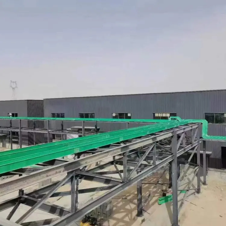
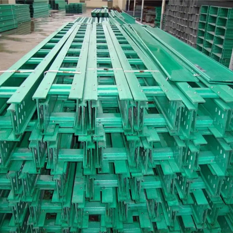
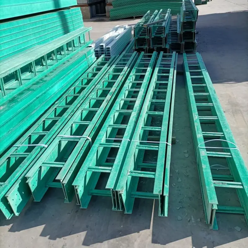
FRP cable channel trays and cable ladders are manufactured by pultrusion and molded processes into ladder-type, channel (U-section), perforated and solid-bottom profiles. They are designed to carry power and control cables where corrosion, electrical insulation, low weight and long service life are required. FRP systems can include covers, splice plates, splice kits, support brackets and specialized fittings to create complete cable-management systems for industrial plants, offshore platforms and utility installations.
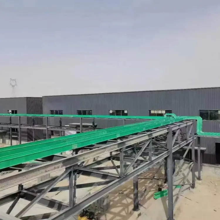 Why choose FRP cable trays & ladders?
-
Superior corrosion resistance — resists saltwater, acids, alkalis and industrial atmospheres far better than uncoated metal trays, making FRP ideal for coastal, chemical and wastewater installations.
-
Non-conductive / electrically safe — FRP eliminates the need for bonding/grounding required for metallic trays when routing live conductors.
-
Fire-performance options — manufactured and selected to meet fire performance requirements such as ASTM D635 / ASTM E84 or equivalent; fire-retardant resin grades are available.
-
Lightweight & easy to install — significantly lighter than steel trays (reduces lifting, faster install, lower transport costs).
-
Low maintenance & long lifecycle — no painting or cathodic protection, reducing lifecycle cost in corrosive environments.
Typical product types & profiles
Fiberglass Cable Ladder (ladder-type)
Open-rung design for ventilated cable routing, improved heat dissipation, and easy cable laying. Rungs are pultruded or molded and mechanically fastened to side rails. Typical rung spacings and designs comply with industry practice (e.g., 6″, 9″, 12″ options).
FRP Channel Tray (U-section / channel)
Solid or ventilated channel with side rails and optional cover — used where additional lateral containment, dust protection or mechanical protection is required. Channel trays frequently include bolt-on covers and I-beam style rails for extra stiffness.
Perforated & Solid-Bottom Trays
Perforated trays balance ventilation and cable support; solid-bottom trays provide full support and protection for sensitive or tightly bundled cable runs.
Standards & compliance
FRP cable channel trays are commonly manufactured and specified to align with national and industry standards for cable management and composite materials. Typical references include CSA / NEMA cable tray standards, ASTM test methods for flame and mechanical behavior (ASTM D635, ASTM E84) and manufacturer technical specs for pultruded shapes. Always request product data sheets and certified test reports for project submittals.
Technical specifications
Note: Values below are industry-typical. For project design use the manufacturer’s datasheet, load tables and span charts.
Materials & resins
-
E-glass fiber reinforcements with polyester, isophthalic polyester, or vinyl-ester resins; fire-retardant formulations available.
Common physical / mechanical characteristics (typical)
-
Glass content: ~55–65% by weight (pultruded profiles).
-
Density: ≈1.6–2.0 g/cm³ (material dependent).
-
Flame behavior: Can meet ASTM D635 / ASTM E84 ratings when specified as fire-retardant.
Common sizes & lengths of FRP cable channel tray
| Material | Support and hanger span
mm |
Safe working load | Calorific value(≤)mm | ||
| Side height 100mm | Side height 150mm | Side height 2000mm | |||
| FRP | 2000 | 550 | 1100 | 1750 | 10 |
- Products size
- Trough-type FRP cable tray: common specification, thickness and weight
| Size (mm) | Thickness (mm) | Weight (kg) | Size (mm) | Thickness (mm) | Weight (kg) |
| 50*50 | 2.5/2.6 | 1.2 | 300*150 | 3.8/3.4 | 6.0 |
| 100*50 | 3.0/3.0 | 1.9 | 300*200 | 4.0/3.4 | 7.0 |
| 100*100 | 3.0/3.0 | 2.4 | 400*100 | 4.0/3.8 | 7.1 |
| 150*100 | 3.0/3.0 | 3.1 | 400*150 | 4.0/3.8 | 8.0 |
| 200*100 | 3.0/3.0 | 3.8 | 400*200 | 4.5/3.8 | 9.8 |
| 200*150 | 3.3/3.0 | 4.5 | 500*200 | 4.5/4.2 | 11.9 |
| 200*200 | 3.6/3.0 | 5.4 | 600*150 | 4.7/4.0 | 13 |
| 250*150 | 4.0*3.2 | 5.7 | 600*200 | 5.0/4.0 | 13.8 |
| 300*100 | 3.5/3.4 | 5.2 |
- Ladder-type FRP cable tray: common specification, thickness and weight
| Size (mm) | Thickness (mm) | Weight (kg) | Size (mm) | Thickness (mm) | Weight (kg) |
| 200*100 | 3.6/3.0 | 4.5 | 500*100 | 3.6/3.5 | 7.6 |
| 200*150 | 3.9/3.0 | 5.6 | 500*200 | 3.9/3.5 | 9.1 |
| 200*200 | 3.9/3.0 | 6.0 | 600*100 | 3.6/4.0 | 9.0 |
| 300*100 | 3.6/3.4 | 5.5 | 600*150 | 3.9/4.0 | 10 |
| 300*150 | 3.9/3.4 | 6.6 | 600*200 | 3.9/4.0 | 10.5 |
| 300*200 | 3.9/3.4 | 7.0 | 800*100 | 3.6/4.8 | 12 |
| 400*100 | 3.6/3.5 | 6.5 | 800*150 | 3.9/4.8 | 13.1 |
| 400*150 | 3.9/3.5 | 7.5 | 800*200 | 3.9/4.8 | 13.5 |
| 400*200 | 3.9/3.5 | 8.0 |
- TEST REPORT
Samples number: 20210608434 Sample size: PCT250x150x2mm
|
Test items |
technical requirement | Test result | ||
| Test value | Single conclusion | |||
| Appearance quality | The surface of the product shall be flat and smooth, with uniform color, and shall be free of wrinkles, cracks, particles, glue flow, resin peeling, fiber exposure and surface sticking. | Meet the requirements | qualified | |
| The glue content is uniform, the curing is stable, and there is no delamination. The accumulated area of bubbles on the surface of a single product shall not be greater than 100mm2/m2, and the maximum area of a single bubble shall not be greater than 15mm2. | ||||
| Structure size
mm |
Width | 250±2 | 250 | qualified |
| Height | 150±2 | 150 | qualified | |
| Thickness | 2(0, +0.2) | 2.2 | qualified | |
| tensile strength Mpa | direction | ≥560 | 897 | qualified |
| bending strength
Mpa |
direction | ≥270 | 1237 | qualified |
| impact strength kJ/m2 | ≥200 | 415 | qualified | |
| Barcol hardness | ≥45 | 56 | qualified | |
| Density g/cm3 | ≥1.9 | 2.1 | qualified | |
| Load deformation temperature ℃ | ≥150 | >160 | qualified | |
| Oxygen index % | ≥28 | 28 | qualified | |
Load & span guidance
FRP cable channel trays are supplied with manufacturer load/span tables and recommended span centers for given tray widths, rung spacing and resin system. For all structural designs, use the supplier’s span tables and consider dynamic loads, concentrated cable bundles, and thermal expansion. If your project requires a specific working load (kg/m or N/m), request the manufacturer’s certified load tables for the selected profile and resin grade.
Advantages
-
Long service life in corrosive service — avoids rust and coating failures.
-
Electrical isolation — reduces stray currents and galvanic corrosion concerns.
-
Faster installation — lighter parts, fewer lifts and bolt-together accessories.
-
Low total cost of ownership — less maintenance, less replacement frequency in aggressive environments.
-
Customizable system — covers, splice kits, bends, tees, reducers, supports, and fire-rated formulations available.
Comparison: FRP Cable Tray vs Steel / Aluminum / GRP alternatives
| Property | FRP Cable Tray (this product) | Galvanized Steel | Aluminum | HDG Steel with Cover |
|---|---|---|---|---|
| Corrosion resistance | Excellent (inorganic chemical & salt resistance). | Poor without coatings; coatings degrade | Good but galvanic risk vs dissimilar metals | Moderate; coatings needed |
| Electrical conductivity | Non-conductive (insulating) | Conductive | Conductive | Conductive |
| Weight | Lightweight (≈1/3 of steel by weight for similar geometry). | Heavy | Medium | Heavy |
| Fire performance | Fire-retardant grades available (ASTM D635/E84). | Non-combustible | Non-combustible | Non-combustible |
| Maintenance | Very low | High (painting, corrosion control) | Medium | High |
Installation & fabrication notes
-
Cutting & drilling: Use carbide saw blades and HSS drill bits; control dust and use PPE. FRP chips are abrasive.
-
Fastening: Use stainless steel or corrosion-resistant fasteners and isolate dissimilar metals to avoid galvanic corrosion.
-
Supports & spans: Install supports at manufacturer-recommended centers; use continuous supports for solid bottom trays when required.
-
Covers & sealing: Bolt-on covers improve mechanical protection and weather resistance; use neoprene gaskets where water ingress must be prevented.
Warranty, QA & quality
-
Request manufacturer Product Data Sheet (PDS), Material Test Reports, and third-party flame test certificates where fire performance matters.
-
For critical projects, require lot traceability, ISO production certification and sample coupons for on-site verification.
FAQ
Q1 — Are FRP cable channel trays suitable for outdoor marine environments?
A: Yes — when specified with a UV-stable, vinyl-ester or isophthalic resin system, FRP trays resist salt spray and marine corrosion. Request the manufacturer’s marine exposure data.
Q2 — What flame rating is available for FRP cable channel trays?
A: Fire-retardant FRP trays can be supplied to meet ASTM D635 / ASTM E84 (surface burning) requirements — ask for certified test reports for the selected resin grade.
Q3 — How do I specify span and load for an fiberglass cable ladder?
A: Provide tray width, rung spacing, expected cable weight per meter, and chosen resin/section. The manufacturer will supply a span table showing maximum span for given loads.
Q4 — Can FRP cable channel trays be bonded or must they be bolted?
A: Both are possible. Most installations use mechanical fasteners and splice kits; adhesive bonding is used for some specialized applications—confirm with supplier.
Q5 — What are standard delivery lengths?
A: Common stock lengths are 3 m, 4 m and 6 m; custom lengths and pre-cut sections are available from many manufacturers.