Sight Glass Leakage: Root Causes and Field Diagnosis
In chemical, power, pharmaceutical, and oil & gas plants, a sight glass is not a simple viewing window. It is a safety accessory within the pressure boundary. When it leaks, the risk is not just a minor drip — it is a potential loss of containment.
Yet in many plants, sight glasses are still treated as ordinary wear parts. After a leak, maintenance teams replace the glass and restart the system without identifying the root cause. The same failure then repeats. In severe cases, the glass bursts under pressure.
This article explains how to correctly identify the leak type, diagnose the most common root causes, and prevent recurrence.
1. The First Critical Step: Identify the Leak Type
Sight glass leakage falls into two fundamentally different categories, and misjudging the type is the most common field mistake.
Sealing face leakage
Leakage occurs at the contact interface between the glass and the flange or cover plate. Media seeps along the gasket and sealing face. The glass body itself often remains intact.
Glass body penetration leak
Cracks, pinholes, or penetrating defects appear in the glass surface. Media escapes directly through the glass. This indicates loss of structural integrity and possible risk of sudden rupture.
To determine the leak type:
Inspect visually. Sealing face leaks show wetting or crystallization around the flange perimeter. Glass body leaks show visible cracks or pinholes on the glass surface.
For low-pressure service, use a soap bubble test. Bubbles at the flange edge indicate a sealing face leak; bubbles on the glass surface indicate a glass body leak.
For high-pressure or hazardous media, perform dye penetrant testing after shutdown.
Note: Media from a sealing face leak can flow along the flange edge and look like a glass surface leak. Clean the area first, wait a few minutes, and observe where the liquid appears first.
2. Sealing Face Leakage: The Dominant Failure Mode
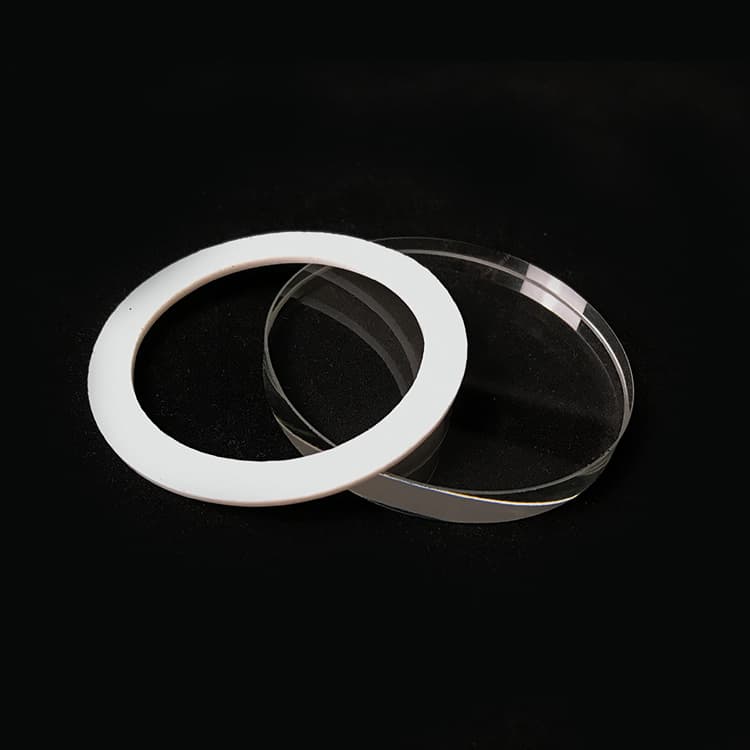
Field experience shows that approximately 80% of sight glass leaks originate from the sealing interface, not the glass body. The most common causes are gasket failure, bolt preload problems, sealing face damage, thermal cycling, chemical attack, and external load.
2.1 Gasket Failure
The gasket is the weakest point in a sight glass assembly.
Common mechanisms:
Chemical incompatibility — the gasket swells, hardens, or dissolves in the process media.
Thermal aging — high temperature or thermal cycling reduces elasticity and compression recovery.
Installation damage — scratches, twisting, or misalignment during assembly.
After removal, a gasket that is discolored, swollen, brittle, or hardened with compression set above 30% has already lost most of its sealing capacity.
2.2 Bolt Preload Problems
Bolt preload creates the seating force on the gasket. Incorrect preload is a major cause of leaks.
Typical issues:
Insufficient torque — sealing force below the minimum required by system pressure.
Uneven torque — torque variation above ±10% can cause local seal failure.
Creep relaxation — at temperatures above 200°C, carbon steel bolts can lose 30–50% of their preload.
Excessive torque — can crush the gasket or create dangerous stress in the glass.
2.3 Sealing Face Damage
Scratches, corrosion pits, or flatness deviation on the flange face create leak paths that a gasket cannot fully seal. Radial scratches across the sealing face are especially dangerous because they provide a direct channel for media to escape.
2.4 Thermal Cycling
Different expansion rates among flange, bolts, glass, and gasket cause micro-movement at the sealing face. This accelerates gasket wear and stress relaxation. Equipment that experiences frequent startup and shutdown above 150°C, steam purging, or large day-night temperature differences is particularly at risk.
2.5 Chemical Attack
Wrong gasket material or long-term media contact can degrade both the gasket and the glass surface. Alkaline media, in particular, can roughen the glass surface and destroy the sealing contact with the gasket.
2.6 External Load and Vibration
Piping stress and equipment vibration can act directly on the sight glass flange. Unsupported pipe spans, missing expansion compensators, and nearby pumps or compressors can all cause uneven bolt loading or gradual loosening.
3. Glass Body Failure: Less Common but More Dangerous
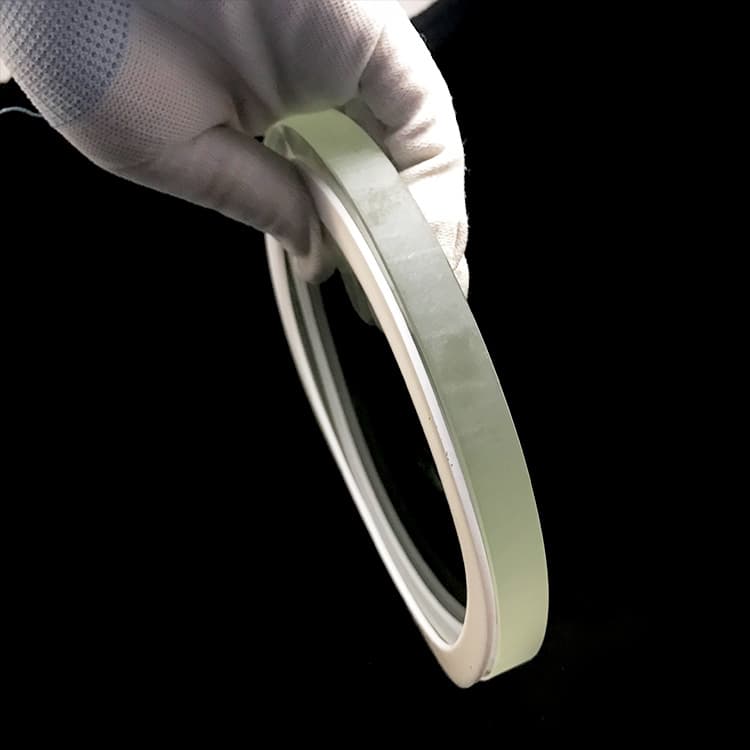
When the glass itself leaks or breaks, the failure is more serious. The main causes are:
Thermal shock — a large temperature difference creates internal stress that exceeds the glass strength. Crack pattern is typically radial or net-like.
Overpressure — pressure exceeds the design rating. This usually produces total fragmentation or deep radial cracks from the center outward.
Mechanical impact and scratches — surface scratches become stress concentration points, and cracks can later develop under normal working pressure.
Chemical attack — alkaline media attack the glass surface, reducing strength and causing fogging or roughening.
Manufacturing defects — bubbles, stones, or striae inside the glass act as crack initiation points.
4. Quick Root Cause Reference Table
| Field Finding | Likely Failure Mode |
| Gasket swollen, discolored, brittle | Chemical incompatibility |
| Gasket hardened, high compression set | Thermal aging |
| Bolt torque generally low | Insufficient torque or creep relaxation |
| Large torque difference between bolts | Uneven tightening |
| Radial scratches on flange face | Sealing face damage |
| Loose when hot, normal when cold | Thermal cycling |
| Glass surface roughened or fogged | Chemical attack |
| Radial cracks, temperature change history | Thermal shock |
| Total glass fragmentation | Overpressure |
| Loose bolts, no pipe expansion compensation | External load or vibration |
5. Prevention: Key Points
Effective prevention starts before installation and continues during operation.
Selection
Choose glass material according to media chemistry and temperature. Borosilicate glass suits most chemical service; aluminosilicate glass suits higher temperatures.
Select gasket material carefully. PTFE for highly corrosive media, flexible graphite for high temperature, EPDM for hot water and steam.
Confirm the sight glass pressure rating is not lower than equipment design pressure. Remember that glass pressure capacity derates at high temperature.
Installation
Clean the flange sealing face thoroughly before assembly.
Inspect the gasket for damage before installation.
Tighten bolts in a diagonal sequence in 2–3 steps to the specified torque. Never rely on feel or assume “tighter is better.
Operation
Perform routine visual inspection for cracks, corrosion, and leakage signs.
Control temperature change rates. Keep heating rate below approximately 5°C per minute during startup and steam purging.
For high-temperature service, recheck bolt torque within 24–48 hours after first startup.
6. Conclusion
Sight glass leaks should never be treated as simple part replacement jobs. The correct approach is to first identify whether the leak is from the sealing face or the glass body, then find the root cause, apply the right repair, and implement preventive measures.
Since most leaks come from the sealing interface, start with the gasket, bolts, and sealing face. Build simple records of inspection findings, installation torque, and replacement history. These data make future failures easier to diagnose and prevent.
When sight glasses are managed as safety-critical accessories, plants move from reactive repair to proactive reliability — and leak risk approaches zero.